ESIM-FGS2 Oil and Gas Gathering and Transportation Simulator
- Reliability
- Stable and reliable software and hardware
- Reality
- Highly realistic 3D scene display
- Service
- Timely and considerate after-sale service
1. Introduction
ESIM-FGS2 The oil and gas gathering and transportation simulation training system is developed by Southwest Petroleum University and Chengdu Esimtech Petroleum Equipment Simulation Technology Exploitation Co, Ltd. It is a system with advanced technology and complete functions which can satisfy the training requirements of oilfields.
The oil and gas gathering and transportation simulation training system is the combination of petroleum engineering, oil and gas transportation and computer technology, virtual reality and computer simulation technologies. The system can enable students to master the inner structure and working theories of the devices, learn the typical stations and process of this section. Through the training and test of this system, students can master the working theories and usage of various devices and can treat the common problem well.
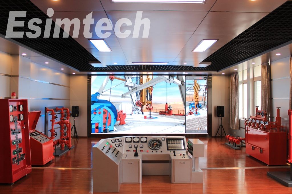
The system calculates the pressure, flow rate and temperature by the method of flow coupling method. The advanced mathematical models make training more vivid as in the real environment. 2D flow state is displayed on the large LCD monitor, which makes the process clear and easy to understand. Therefore, it not only saves the training time, but also strengthens the students’ knowledge.
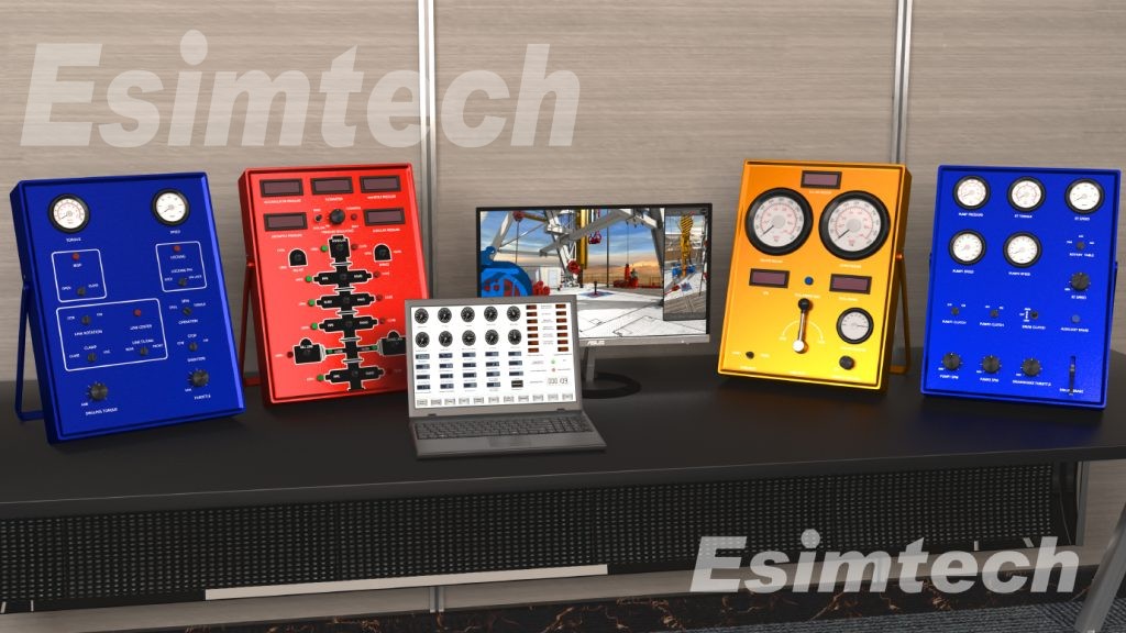
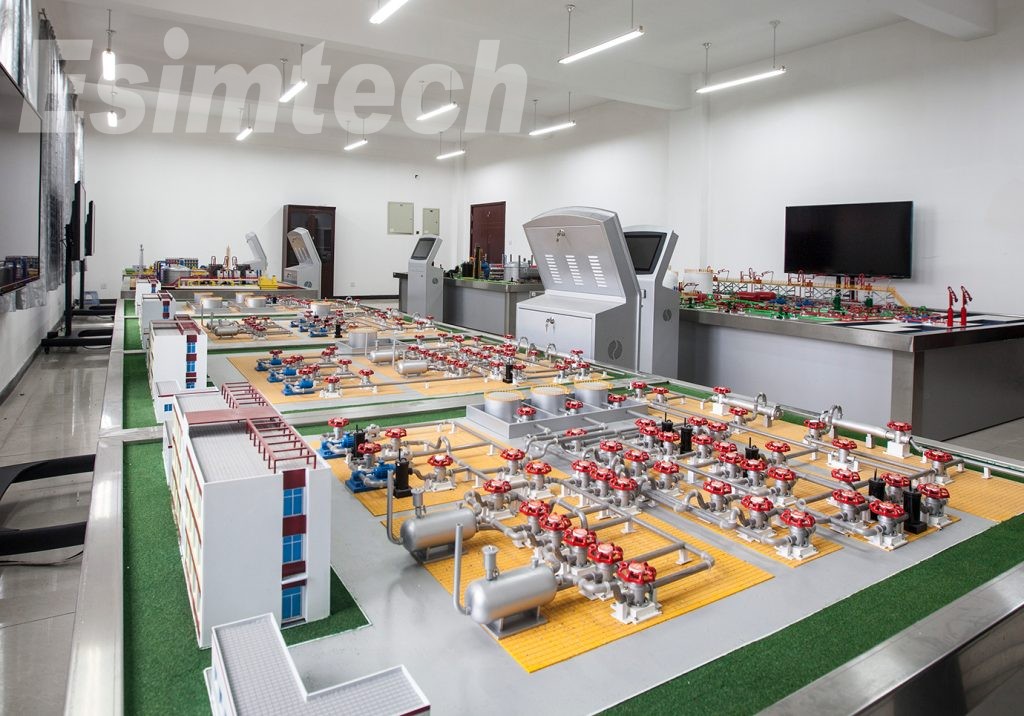
The system consists of joint station, crude oil pipeline, natural gas boosting and distributing, LNG receiving station, oil depot and other accessory software. The appearance of the consoles is the same as the real equipment. The layout of panels, operation methods and parameter displaying are the same as those in real site. The hardware system is designed according to industrial standard; data acquisition and controlling system is constructed by PLC, which ensures the stability of the equipment. The system has the advantage of low input and maintenance cost with no security risk.
2. System Component
2.1 Major Hardware
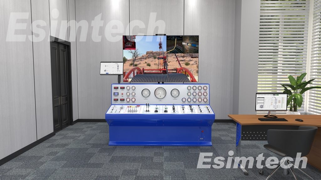
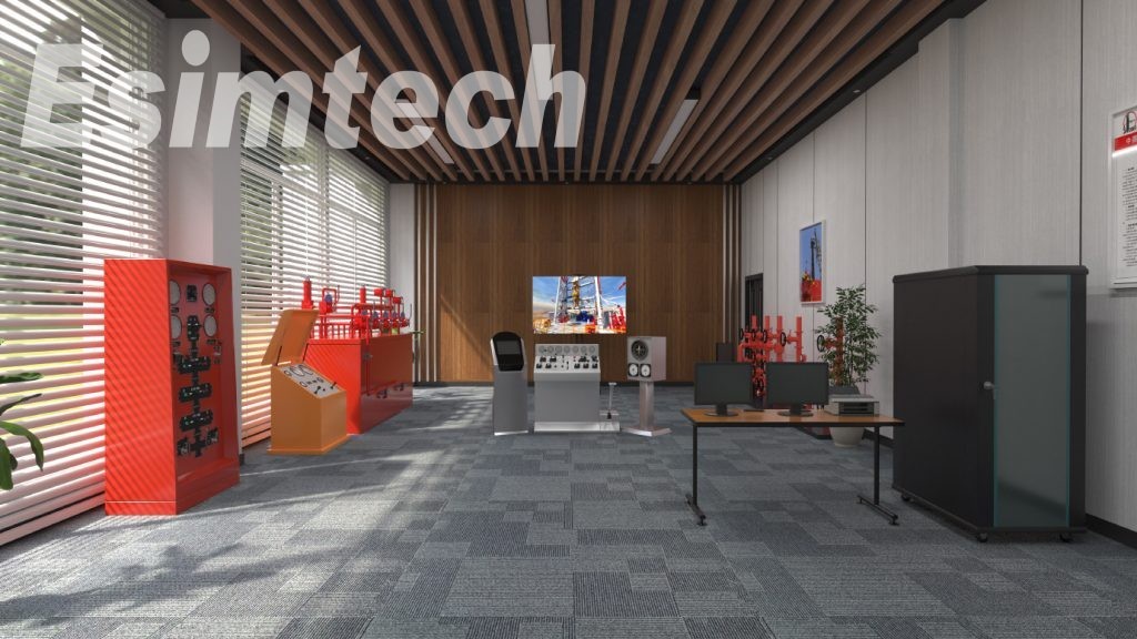
The hardware system structure is as shown in figure 1. The whole system is composed of LNG receiving station, joint station, crude oil pipeline station, natural gas booster and distributing station and oil depot. Each part has PLC, controlling computer and LCD monitor displaying 2D flow. There is also a graphics computer and a projector to projecting the flow to a large screen. Users can also present the working principle of various devices on the large screen.
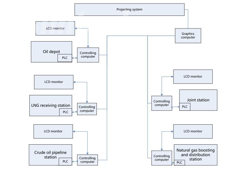
Figure 1 System hardware framework
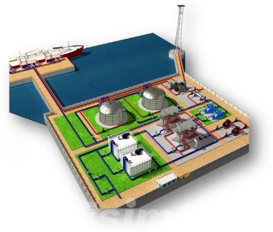
(1) LNG receiving system is used to simulate the LNG receiving and transferring. This station is composed of harbor, two large storage tanks, two compressors, two seawater pumps, two booster pumps, two seawater evaporators and two burning evaporators.
All the pipes on the console present the flowing state in the form of flash light. Parameters as pressure are displayed on the LCD monitors. All valves and devices on the console can be operated. LCD monitor can display the flowing state at real time according to the actual operation, and can give prompts if there’s any operation error.
|
|
LNG receiving station Plastic sand table LED dynamic flow indication |
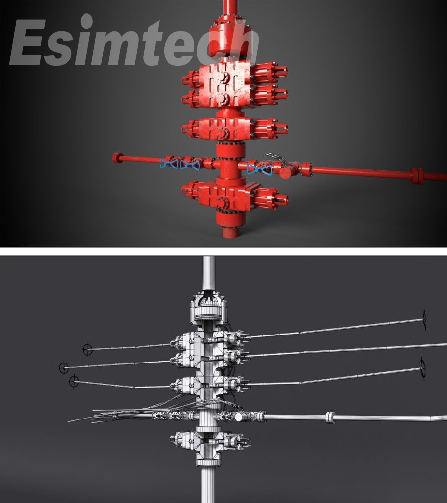
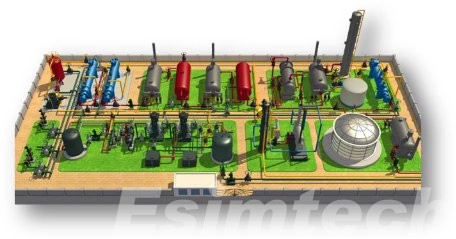
(2) Joint station system has the functions of processing crude oil, injecting water and processing waste water. This station is composed of metering separator, crude oil dehydration device, waste water processing device, crude oil transferring device and other accessories.
All pipes on the console shows the flowing condition by flash lights. Parameters as pressure are displayed on monitors. All valves and devices on the console can be operated. Monitors may give prompts of operational error by display the real time flowing condition in the pipeline.
|
|
Joint station Plastic sand table LED dynamic flow indication |
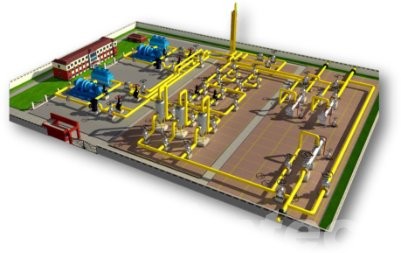
(3) Boosting and distribution station system simulates natural gas booster and distribution station used to increase pressure by electric booster pump. This station is composed of a unit of pig receiving device, two sets of pig launching devices, three units of whirlwind filtering separator, two units of electric booster pumps and metering devices.
All pipes on the console shows the flowing condition by flashes. Parameters as pressure are displayed on monitors. All valves and devices on the console can be operated. Monitors may give prompts of operational error by display the real time flowing condition in the pipeline.
|
|
Natural gas boosting and distribution station Plastic sand table LED dynamic flow indication |
(4) Crude oil pipeline system is used to simulate the whole delivering process. It contains four parts, which are crude oil pipeline first station, crude oil, tank to tank intermediate station (unsealed transferring middle station), pump to pump transfer middle station (sealed transferring middle station), and crude oil pipeline final station. Each station is equipped with corresponding furnace, pump, pipe pig and storage tank, which can simulate different working conditions of crude oil pipeline.
All pipes on the console shows the flowing condition by flashes. Parameters as pressure are displayed on monitors. All valves and devices on the console can be operated. Monitors may give prompts of operational error by display the real time flowing condition in the pipeline.
|
|
Crude oil pipeline station Plastic sand table LED dynamic flow indication |
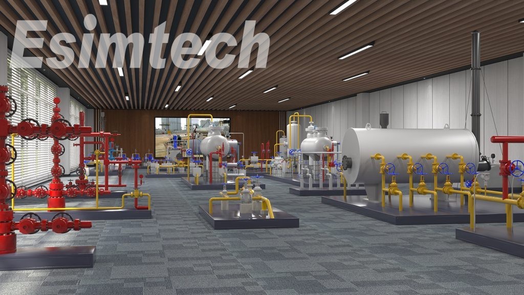
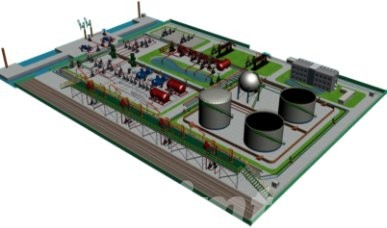
(5) Oil depot is designed according to real refined oil depot. There are typical operation process such as oil storage vessels, railway releasing device, water route releasing device, automobile dispatching device, canning device and central pump station, equipped with three kinds of storage tanks, vacuum pump and centrifuge pump, which and realizes the process of marine loading and unloading, railway loading and unloading, highway loading, canning and switching.
All pipes on the console shows the flowing condition by flashes. Parameters as pressure are displayed on monitors. All valves and devices on the console can be operated. Monitors may give prompts of operational error by display the real time flowing condition in the pipeline
|
|
Refined oil depot Plastic sand table LED dynamic flow indication |
2.2 System Software
2.2.1 Esimtech LNG simulation and training software
(1) Fluid calculating software module
(2) Equipment controlling software module
(3) Monitor controlling
(4) 2D flow displaying
2.2.2 Esimtech crude oil pipelines simulation and training software
(1) Fluid calculating software module
(2) Equipment controlling software module
(3) Monitor controlling
(4) 2D flow displaying
2.2.3 Esimtech joint station simulation and training software
(1) Fluid calculating software module
(2) Equipment controlling software module
(3) Monitor controlling
(4) 2D flow displaying
2.2.4 Esimtech booster and distribution station simulation and training software
(1) Fluid calculating software module
(2) Equipment controlling software module
(3) Monitor controlling
(4) 2D flow displaying
2.2.5 Esimtech refined oil depot simulation and training software
(1) Fluid calculating software module
(2) Equipment controlling software module
(3) Monitor controlling
3. System Functions
3.1 Functions and Features
(1) The system is designed according to the prototype of real site equipment. The appearance, line connection and operation method are the same as real devices.
2) The system can calculate parameters as equipment working condition and pipe pressure at real time according to students’ operation.
(3) The 3D animation simulates the visualization of real environment, also displays down-hole conditions, device motions and working theories of the devices.
3.2 Training Project
(1) Natural gas boosting and distribution simulation
Distribution process
1) Compressor #1 boosting process
2) Compressor #2 boosting process
3) Compressors parallel boosting process
4) Boosting bypass process
Trans-station process
1) Trans-station process
Pig receiving and launching
1) Pig receiving
2) Pig launching and shutting in
(2) Crude oil long-distance transportation
Initial station process
1) Initial station forward transportation
2) Initial station reverse transportation
3) Initial station pump oil to tank
4) Initial station internal circulation
5) Initial station changing tank
Intermediate station closed transportation process
1) Intermediate station closed transportation forward transportation
2) Intermediate station closed transportation reverse transportation
3) Intermediate station closed transportation trans station
4) Intermediate station closed transportation heat trans station
5) Intermediate station closed transportation pressure trans station
6) Intermediate station closed transportation internal circulation
Intermediate station tank to tank process
1) Intermediate station bypass tank forward transportation
2) Intermediate station bypass tank reverse transportation
3) Intermediate station bypass tank trans station
4) Intermediate station bypass tank pressure trans station
5) Intermediate station bypass tank heat trans station
6) Intermediate station bypass tank internal circulation
7) Intermediate station bypass tank reverse transportation pressure trans station
Final station process
1) Final station forward transportation
2) Final station changing tank
3) Final station oil reception
(3) Joint station
Crude oil processing
1) Metering procedure
2) Crude oil dehydration procedure
3) Crude oil transportation procedure
Waste water process procedure
1) Waste water processing
2) Waste water backwashing
Water injection procedure
1) Pump station
2) Water processing procedure
(4) LNG receiving station
Discharging
1) Discharging LNG to storage tank#1
2) Discharging LNG to storage tank#2
LNG vaporizing/transporting
1) LNG in storage tank#1 vaporized and transported from open shelves typed evaporator
2) LNG in storage tank#2 vaporized and transported from open shelves typed evaporator
3) LNG in storage tank#1 transport from submerged burning evaporator
4) LNG in storage tank#2 transport from submerged burning evaporator
LNG flash distillation
1) LNG in storage tank#1 transported after flash distilling
2) LNG in storage tank#2 transported after flash distilling
3) LNG in storage tank#1 burned after flash distilling
4) LNG in storage tank#2 burned after flash distilling
Circulating in tank
1) Circulating in storage tank#1
2) Circulating in storage tank#2
(5) Refined oil depot
Railway loading and unloading operation
Automobile loading and unloading operation
Water route loading and unloading operation
Switching operation
4. Technical Parameters and Operational Environment
4.1 Technical Parameters
(1) Power supply: 220V/50Hz AC
(2) Power consumption: <6000W
(3) Resolution: 1920*1080
(4) Brightness: >=3000ANSI Lumens
4.2 Operational Environment
(1) Area: >=10*8.5m
(2) Separate equipment power supply from light power supply
(3) Working temperature: 0℃~30℃
(4) Relative humidity: <90%
5. System Whole Layout and Program Running Interface
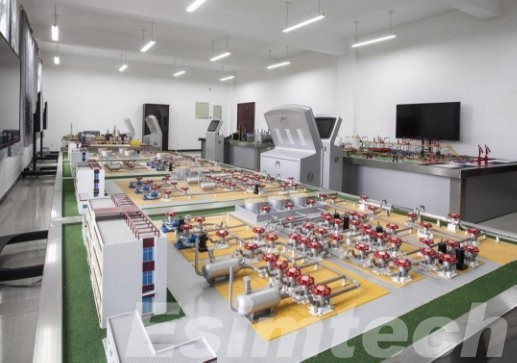
Figure 2 System whole layout
|
|
|
|
|
|
|
|
|
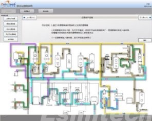
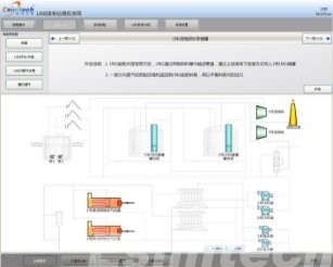
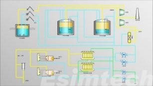
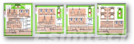
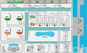
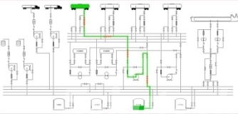
Figure 3 Typical program running interfaces
F&Q
- What is a petroleum simulator?
A simulator is a device that simulates an environment for the purpose of training or research. A drilling simulator is a set of devices that simulates the well site environment, the real operation devices, the operation method, parameter display way, etc. with which trainees can be access to a virtual well site environment, where they can get familiar with the relative devices, how to operate the devices, what phenomenon there will be if there is a problem, what’s happening underground, etc.
- Why is the simulator necessary to oil and gas industry?
Since the beginning of the 20th century, simulators have been used in different industries as tools to train and to facilitate the growth of the operators of the machinery. This type of training is, without a doubt, one of the most effective ways to mitigate labor risks, develop skills needed, and increase productivity.
In oil and gas industry, accidents happen from time to time, such as blowout, H2S leakage, fire, explosion, machinery injuries, etc. Working in oil and gas field is of high risk. According to statistics, almost 36% of these accidents were caused by mistake in operation. Sufficient pre-post training is essential. A simulator makes this possible, which provides a virtual training environment, for new staff the get familiar with the working environment, site scene, and operation devices in advance. With the simulator, new staff can also experience the common incidents which may occur in real operation, and learn to judge and handle of the emergencies. So that in real work, most of the accidents can be judge or avoid in an early stage, and therefore reduces risks and increase production.
- What well control simulations does this well control simulator cover?
In well control operation, pressure control is very important. How the pressure is controlled? In the good control simulator, various scenes of kick can be simulated, both hard and soft shut-in the procedure can be carried out. Meanwhile, various well-killing methods are provided, such as driller’s method, engineer’s method, volumetric method, bullheaded, low choke method, standpipe pressure method, etc.
If you have any needs or questions about Esimtech’s drilling simulator, please feel free to contact us.