ESIM-FWS3 Workover Simulator
- Reliability
- Stable and reliable software and hardware
- Reality
- Highly realistic 3D scene display
- Simulation
- The appearance design, system layout, operation method and parameter display of the console panel is exactly the same as the real equipment.
1. System Components
1.1 Major Hardware
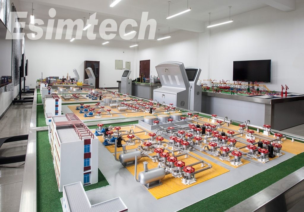
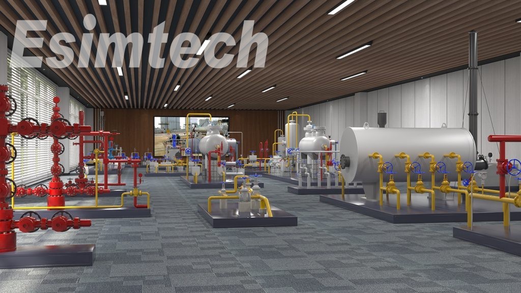
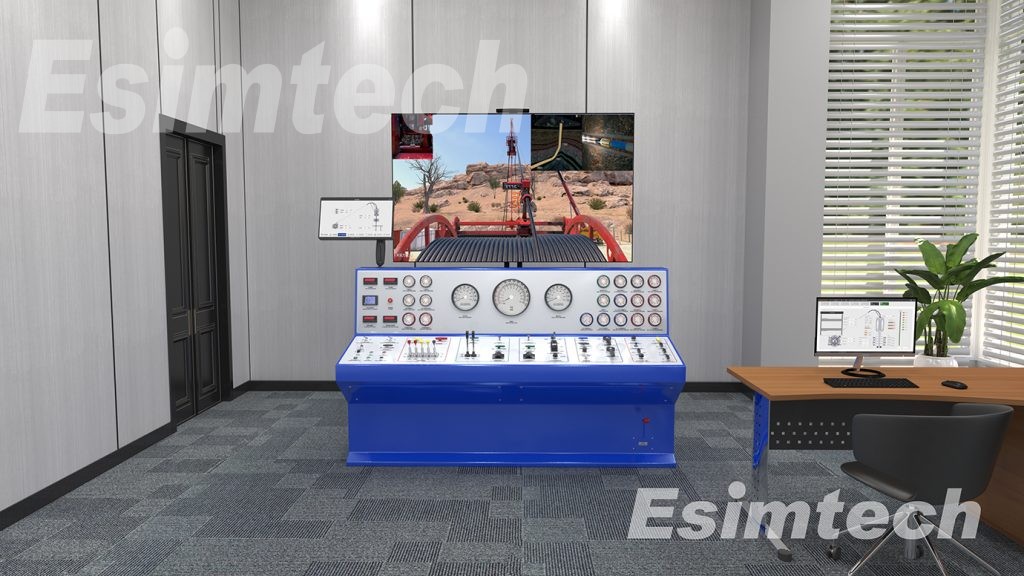
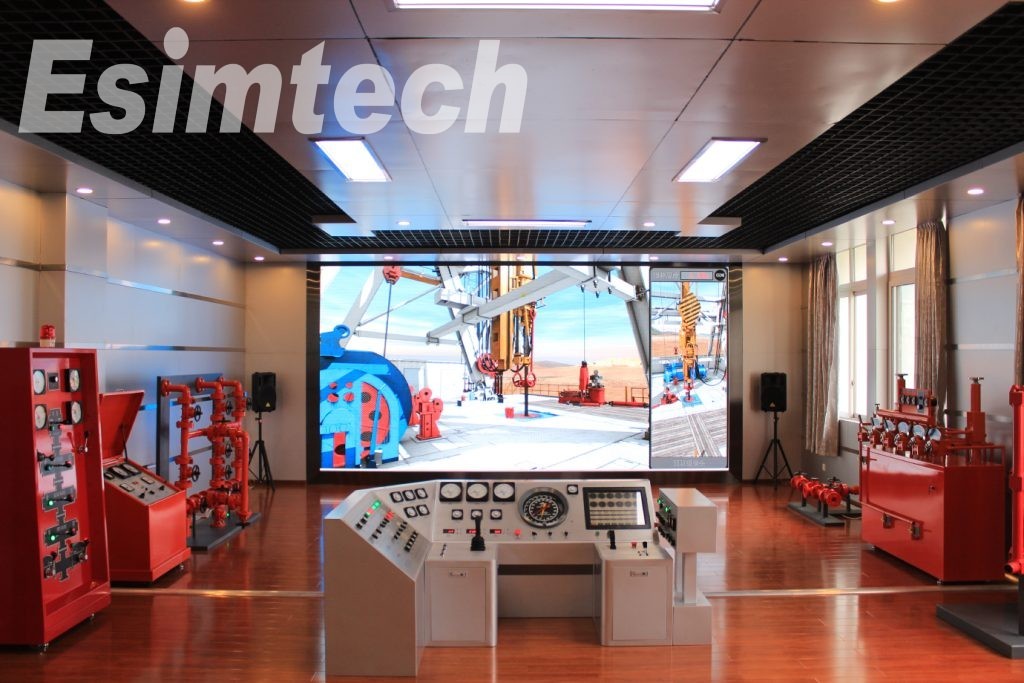
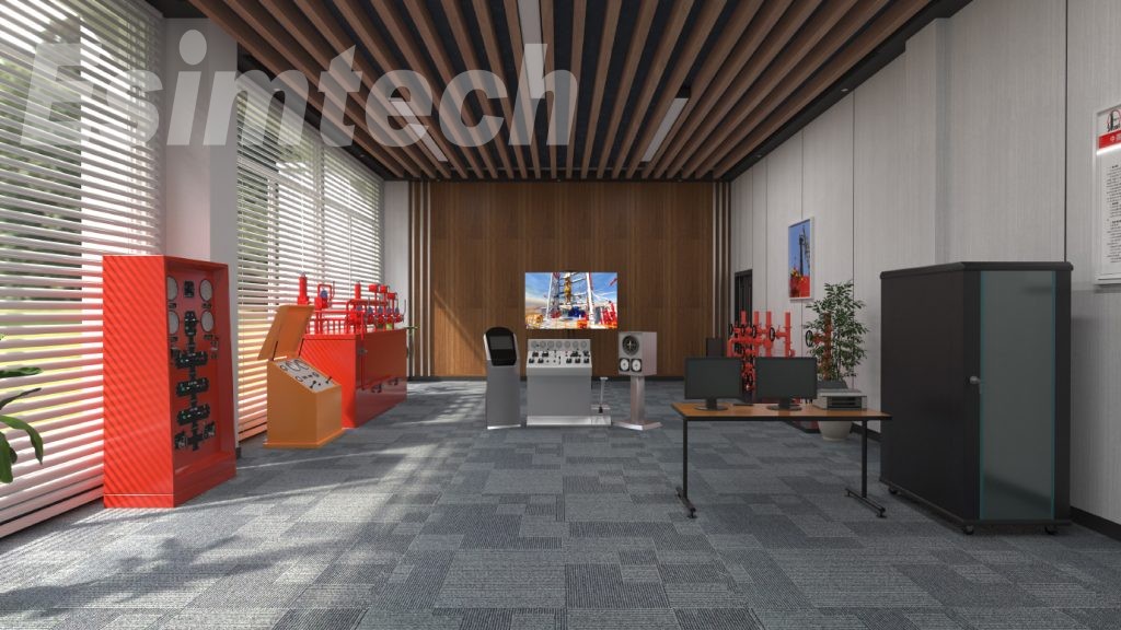
Full-size workover simulation training system is composed of workover console, BOP console, choke console, standpipe manifold, choke manifold, kill manifold, remote console, parameter displaying unit, and scenario displaying system. The hardware devices all simulate the real site devices, which represent the workover operation environment.
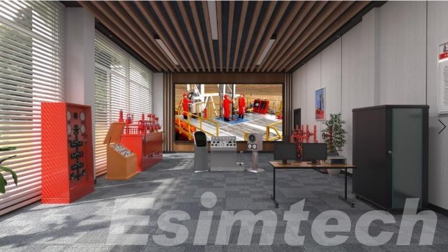
Figure 1 System layout
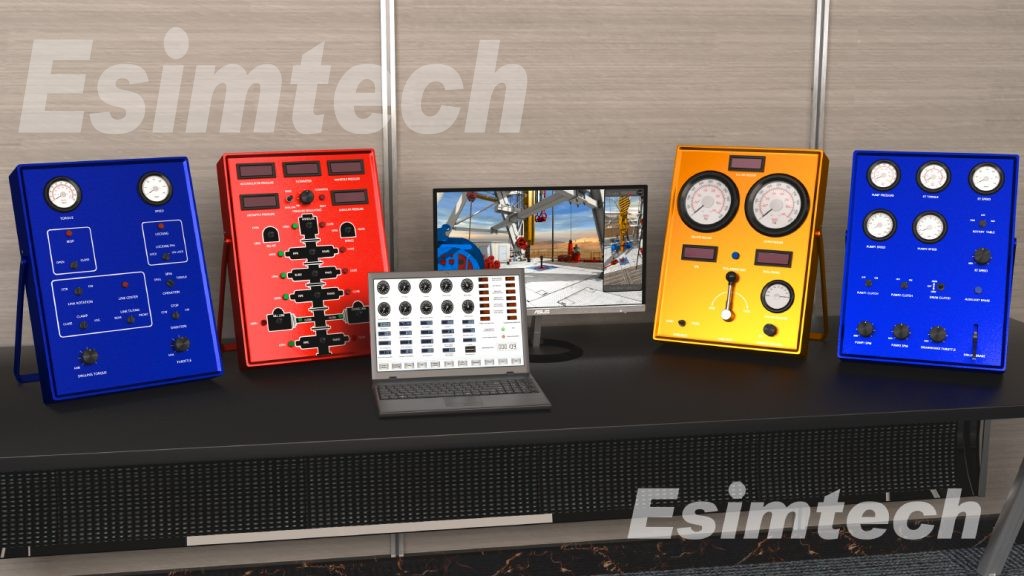
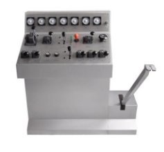
1. Workover console
Work-over console simulates the standard XJ45 driller console. The control and display are the same as real equipment. It can simulate draw-works raising and lowering, mud pump speed regulating, etc.
|
|
1) All metal construction (steelconsole and aluminum panel);simulating XJ45 work-over rig, with band brake system; suitablefor major and minor workover operation. 2) The size is 1110mm*560mm*1250mm |
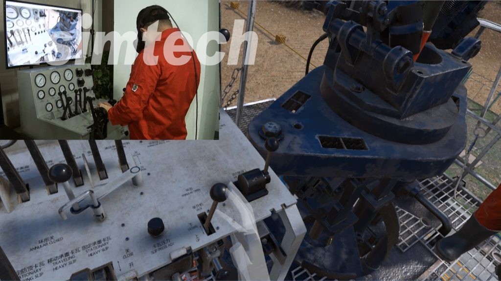
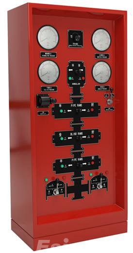
2. BOP console
BOP console resembles conventional products. The operations and parameter displayare the same as real equipment.
|
|
1) All metal construction. The size is 860mm*530mm*1870mm; 2) Adopting “annular-pipe-ram-blind-ram-pipe ram” structure, linked with remote console. |
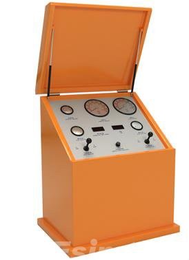
3. Choke console
Choke console resembles conventional products. The operations and parameter display are the same as real equipment.
|
|
1) All metal construction (steel console and aluminum panel);the size is 610mm*830mm*1120mm; 2) Adopting dual hydraulic pressure choke console structure. |
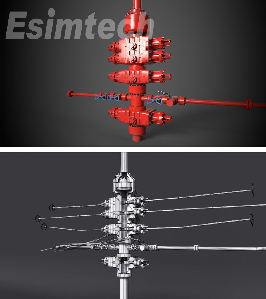
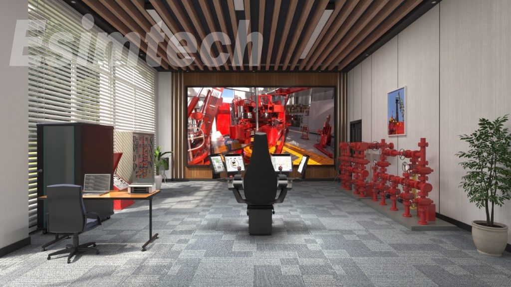
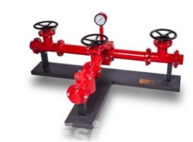
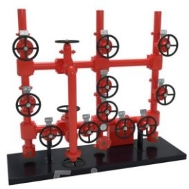
4. Manifold system
Kill manifold, standpipe manifold and choke manifold are designed according to the structure and layout of real manifold. The operations are the same as real equipment.
|
|
1) All metal structure (steel). Thesize is 18800mm*900mm*700mm; 2) Horizontal structure. All valves are operable. Kill manifold pressure is displayed according to operation needs. |
|
|
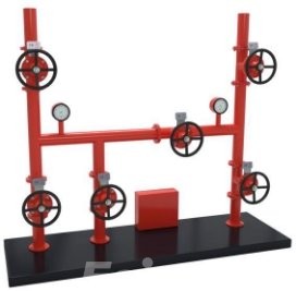
1) All metal structure(steel).The size is 1650mm*650mm*1650mm;
2) Designed according to high-pressure dual hydraulic choke manifold structure, with all valves controllable.Pumpp ressure is displayed according to operation needs.
|
|
|
1) All metal structure(steel).The size is 1800mm*650mm*1750mm; 2) All handwheel aredetected by sensors.All valves are operable;with manual choke and remove hydraulic choke control.Casing pressure is displayed at real-time. |
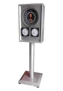
5. Parameter displaying unit
Parameter displaying unit is used to display hook load,WOB,tubing pressure,casing pressure,etc.
|
|
1) All metal structure, separate unit, displaying three important parameters such as load, standpipe pressure and casing pressuring. 2) The size is 500mm*300mm*1705mm |
6. Parameter display station
Displays the workover parameters at real time,the parameter alarm setting can be set in this station and the display and operation of the simulated surface circulation system are all in this station.
|
|
All metal structure.Independent unit, displaying the workover parameters,providing the alarm setting,display and operation of the simulated surface circulation system. |

Display syste madopts LED screen display.
|
|
A.Large size LED true color display system The 3D animation is displayed on LED true color display screen after process by professional graphics processor. • LED P2.5 screen, resolution:1920*1080 • LED screen size: 5400mm(wide)*3215mm(high) (The ultimate installation size and resolution depend on the installation environment |

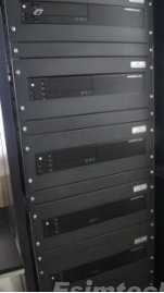
7. 8 Other
|
|
Main components: 1) Parameter computer 2) Master control computer 3) Graphic computer 4) 23-inch monitors*2 5) Computer cabinet*1 6) Sound effect system 7) Printer 8) Instructor desk*1; Chair*2 9) One-key-start system(Power on and power off the system with one key) |
2. System Software
(1) One-key-start controlsoftware
It is used to control the starting up and shutting down of the simulation system. This software also provides the control of scenario shifting of major workover and minor workover.
(2) Master Control Software
a) Student side software module
This module displays the workover parameters, provides alarm setup, and simulates the operation and displaying of surface circulation system.
b) Instructor station software module
This module provides the setup and modification of parameters such as formation parameters,well structure,drill string assembly,pump parameter,mud system parameters,etc.and provides the displaying of parameters at real-time such as tripping speed,WOB,rotary rate,pit gain/loss,return flow,pump speed,flow rate,total strokes,etc.In this module,instructor can set measurement unit,system language,and can control simulation speed.
c) Primary training software module
Provides training on running and pulling pipes, sand washing, lead block printing,etc.
d) Intermediate training software module
Provides training on detecting stuck point, fishing, shaping etc.
e) Senior training software module
Provides training on perforation, scraping, etc.
f) Well control software module
This module controls well control operation,and simulates the displays of well control parameters such as casing pressure,tubing pressure,choke position,workover fluid increase/decrease,bottom hole pressure,etc.Parameters can be displayed in the form of curves at real-time such as tubing pressure,casing pressure,pit gain/loss,bottom hole pressure,formation pressure.
g) Sound effect control module software
Sound of pumps, drawworks, rotary table, etc. on workover site can be simulated.
h) System diagnostic module
Detecting the working state of hardware devices.
i) Students managing module
Graphics Software
a) Drilling-floor-based (major workover) 3D scenario displaying software module
b) Non-drilling floor-based (minor workover) 3D scenario displaying software module
3. Software System Functions
2.1 Sound effect simulation
There is simulation sound when there is corresponding action in the simulation animation such as device collision,running,speed up/down,etc.The simulated sound effect is vivid and close to the sound on real site.
2.2 Simulator function
The simulator is mainly used for training workover driller,drilling crew technicians and workover team leaders.Through the training and test of this system,trainees can master the skills of hard shut-in and soft shut-in,and well killing technology of conventional and unconventional well killing.
The system adopts various mathematical models to simulate various working conditions and parameters of down hole operations,such as pressure,torque,flow rate,etc.and reflect relationships of these parameters to realize training effect of operating on real site
Workover parameters can be set in the system,such as string structure,well structure,formation parameters,device parameters,etc.which makes training more targeted and flexible.The software adopts non-sequence framework,simulating various operations of workover.Virtual reality technology and 3D animation makes up an immersive training environment.
The simulation system is designed according to industrial standard.Data acquisition and control system is constructed by RTU,which ensures the stability of the system.
2.3 Functions andFeatures
1) The system adopts non-sequence simulation software structure. There is no limitation to trainee’s operation sequence. Operators can operate the simulations system randomly, just as operating the real workover rig.
2) The simulator can dynamically simulate the formation kick according to the parameters change such as well depth, mud density formation pressure, bottom hole pressure, formation permeability, etc.
3) After simulation shut-in, operator can record and calculate shut-in tubing pressure and shut-in casing pressure at real-time.
4) During well killing circulation, bottom hole pressure can be adjusted by adjusting casing pressure and tubing pressure with choke valve.
5) During well killing, killing speed can be adjusted at any time.
6) After well killing, killing curves can be generated automatically. The curves including tubing pressure, casing pressure, pit gain/ loss, bottom hole pressure, etc.
7) After simulation kick occurs. Any BOP tools can be chosen to installed, such as BOP wellhead, cock, BOP sub, BOP single, etc.
8) During pulling/ running string. The system can calculate fluctuation pressure.
9) System can simulate the process of hard shut-in and soft shut-in.
10) After shut-in, system can calculate shut-in tubing pressure in the string with cock valve.
11) The system can simulate pressure change by gas migration.
12) During practice and assessment by the simulator. students should observe the parameters and judge the downhole troubles by relevant parameter change.
13) The simulator can simulate two scenarios for practice and assessment: major workover and minor workover.
14) Different parameters can be set in snapshot for practice and assessment, such as formation structure, make-up of string etc
15) The simulator can record student’s operation at real-time and gives out score according to the operation.
16) The simulator can display workover parameters at real-time such as WOB, rotary rate, tubing pressure, flow rate, mud volume, pit volume, trip tank gain/ loss, well depth, string position, hook height, etc.
17) It has alarm setting function. Trainees can set numerous parameter limits. When parameters exceed the set limit value, the system will launch an alarm. And the launching and stopping of the alarm complies with the trainee’s operation, work condition and also graphics. The parameter alarms that can be set include mud gain/ loss alarm, anti-collision upper and lower limits, etc.
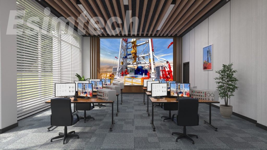
18) The system simulates real site using 3D animation on big screens which shows workover operation scenario, device action and device working principle.
19) The system provide English unit and Metric unit, which can be shifted timely.
20) The system provide Chinese and English language which can be shifted timely.
21) The system has automatic scoring function. It gives scores according to trainee’s operation and level, as well as the reasons that they lost scores, which realizes fairness and equity.
22) The system has trainee information management function
4 Training Projects
(1) Primary workers operation
1) Pulling and running tubing
2) Sand washing
3) Lead-mode printing
(2) Intermediate workers operation
1) Eccentric roller reshaping
2) Fishing with releasing spear
3) Fishing with slider spear
4) Measuring stuck point
(3) Senior workers operation
1) TCP perforation
2) Scraping after perforation
(4) Shutting in operation
With drilling platform
1) Shut-in after kick occurs in rotary operation
2) Shut-in after kick occurs in running and pulling operation
3) Shut-in after kick occurs in tripping large diameter tool operation
4) Shut-in after kick occurs in barren hole
5) Shut-in after kick occurs in wireline perforation operation
Without drilling platform
1) Shut-in after kick occurs in rotary operation
2) Shut-in after kick occurs in running and pulling operation
3) Shut-in after kick occurs in tripping large diameter tool operation
4) Shut-in after kick occurs in barren hole
5) Shut-in after kick occurs in wireline perforation operation
(5) Well killing
1) Driller’s method of well killing
2) Reverse circulation driller’s method of well killing
3) Engineer’s method of well killing
4) Reverse circulation engineer’s method of well killing
(6) Animation display
1) Disassembling Christmas tree—install standpipe BOP
2) Swabbing the well in
3) Reverse circulation well killing
4) Lowering gauge pressure testing
5) Fracturing sand control
6) Screw drill
7) TCP-DST combination test
8) Demonstration of toxic and harmful gases operation
9) Demonstration of installation, inspection and operation of remote console
5. Technical Parameters and Operation Environment
4.1 Technical Parameters
-
Power supply: 110~220V/ 50~60 Hz AC
-
Equipment power consumption: 2.5KW
-
LED screen power consumption: 15KW
4.2 Operation Environment
-
Area:>=40m2
-
Working temperature: 0~30 ℃
-
Relative humidity: <90%
5. Program Interfaces
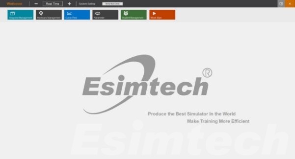
Figure 2 Master control starting interface
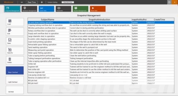
Figure 3 Instructor controlling interface
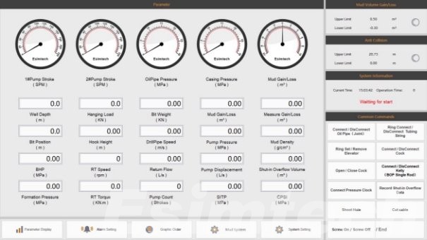
Figure 4 Student operation setup interface
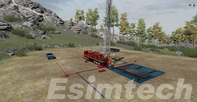
Figure 5 Graphic interface of minor workover
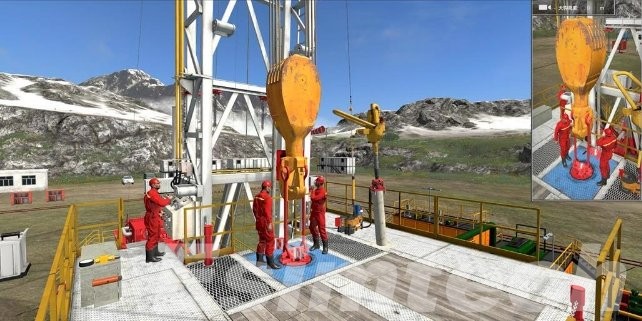
Figure 6 Graphic interface of major workover
F&Q
- Do you have any after-sale service?
Esimtech provides lifetime service support via phone, email or fax at no cost. The simulator is under warranty for a period of 12 months, including updates if released during the warranty period.
- Do you have any certifications?
Esimtech drilling and well control simulator has been approved by IWCF and IADC.
Since establishment, Esimtech has obtained a series of independent intellectual property rights, including invention patents in China and abroad.
Esimtech was granted as “High-tech Enterprise”, and has been awarded the third prize of “Science and Technology Progress”.
Esimtech has also obtained the certificates of ISO 9001, ISO14001 and ISO45001.
- Do you have simulators simulating offshore drilling platforms?
Esimtech provides drilling and well control simulator with offshore platform simulation.
- Is there a complete instruction for use if I ordered?
There will be completely operational instruction and maintenance instruction along with the package.