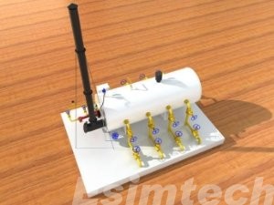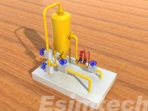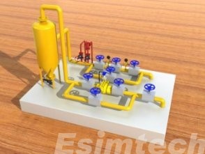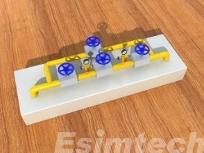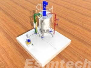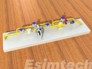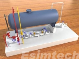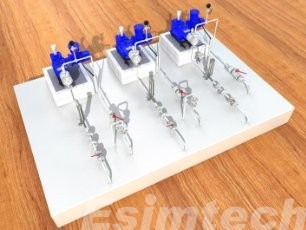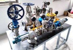
ESIM-FGR3 Gas Production Simulator
- Cutomization
- Customized software and hardware
- Preciseness
- Precise mathematical and physical model
- Reliability
- Stable and reliable software and hardware
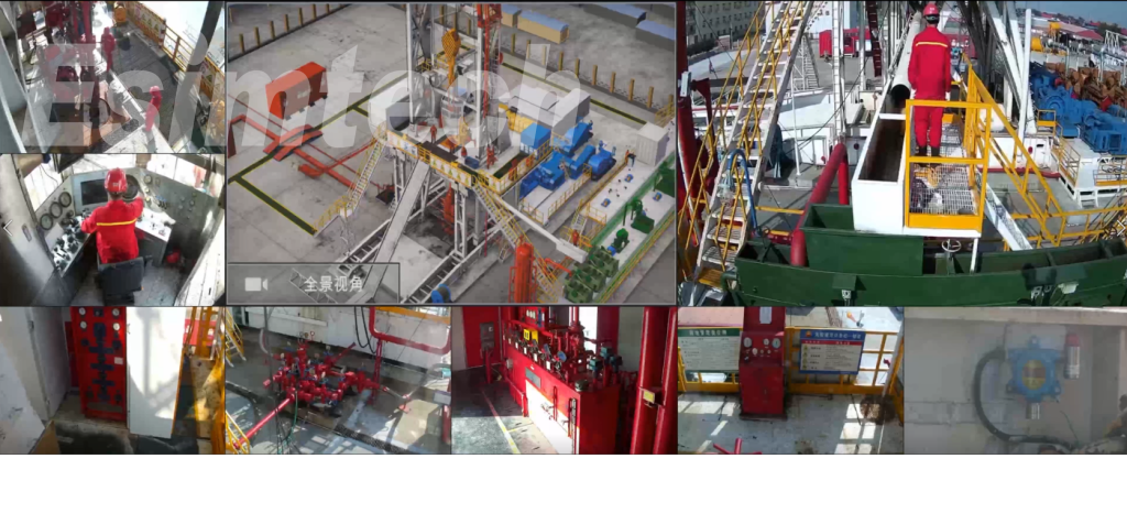
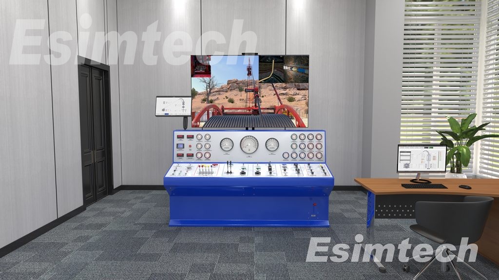
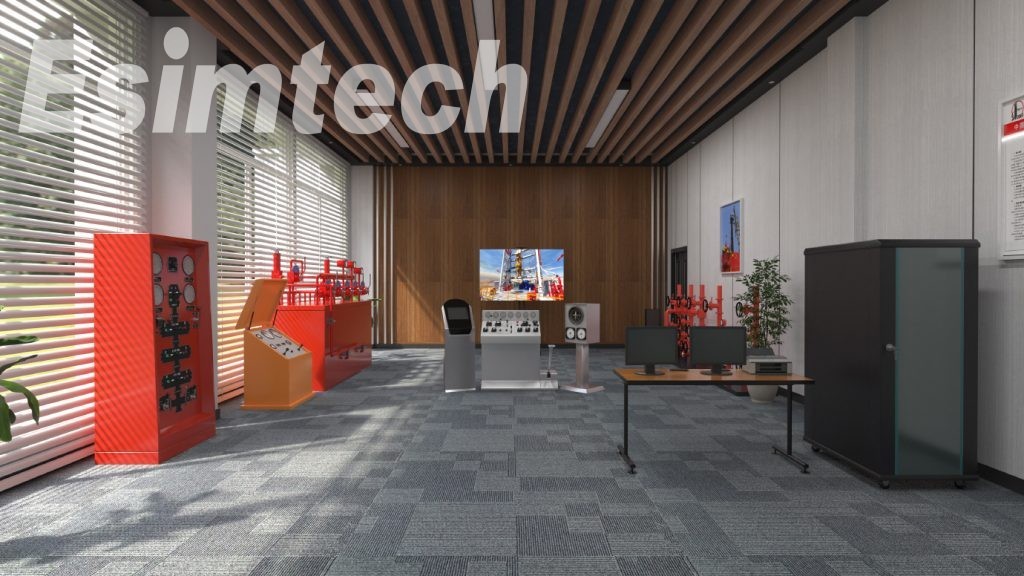
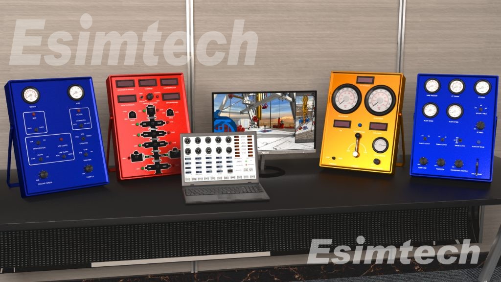
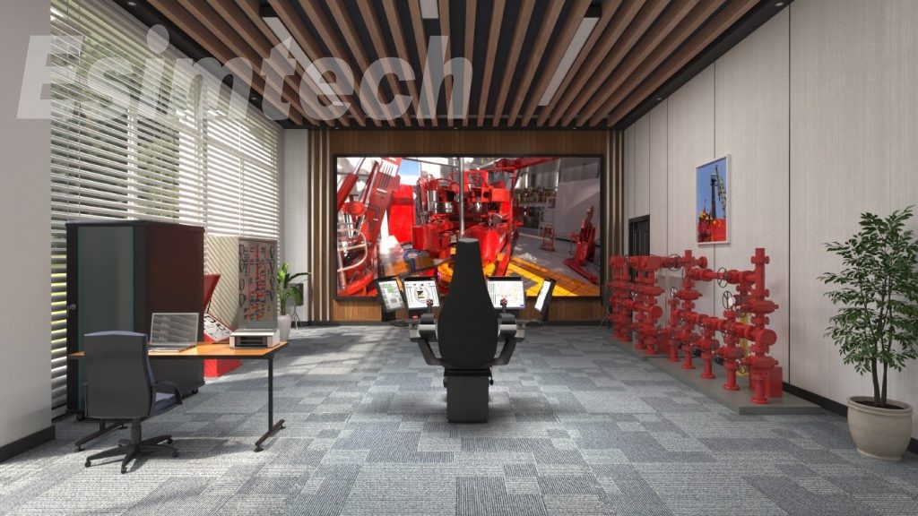
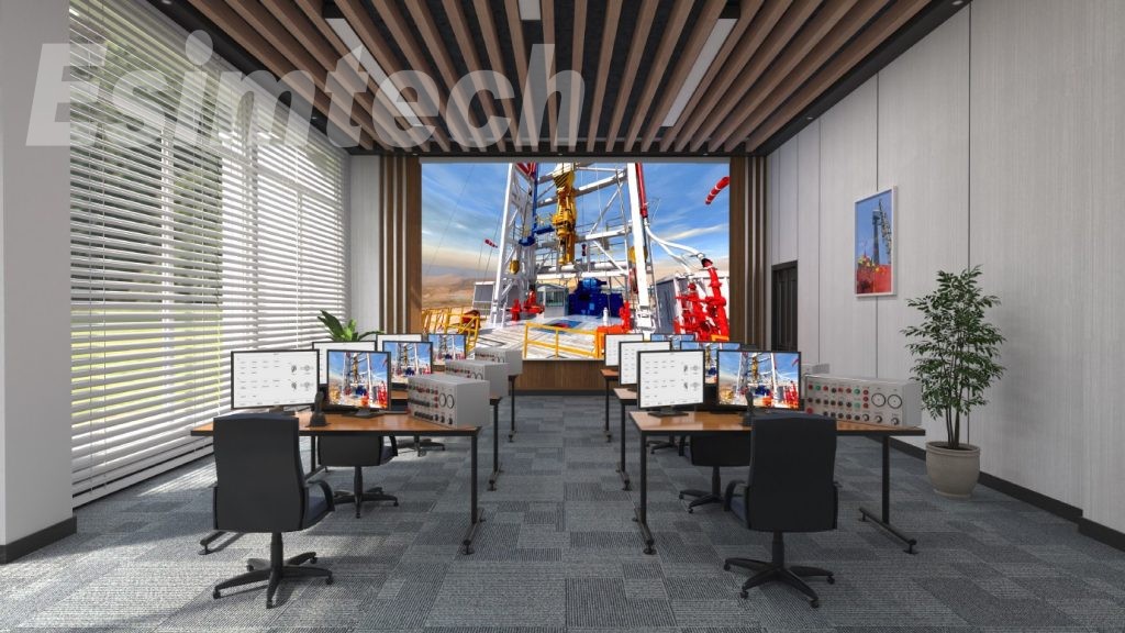
ESIM-FGR3 gas production simulation training system designed by Esimtech enables students to master the inner structure and working theories of various gas production devices, with technologies of petroleum engineering, oil and gas storage and transport, computer, virtual reality.
Through the training provided by this system, students can familiarize typical stations and flows of this section. The training can be provided to primary, intermediate, senior workers, as well as technicians. The working condition of the devices is presented on a large size projecting screen, which makes it easy for students to understand. The simulation system saves training time and also strengthens students’ understanding.
Parameters
| Power supply: | 110~220V/ 50~60 Hz AC |
| Power consumption: | < 6000 Watt |
| Working temperature: | 0℃~30℃ |
| Average time between malfunction: | ≥5000 hours |
Training Items
- Flowing well startup and shutting in
- Pumping unit dewatering startup and shutting in
- Plunger dewatering startup and shutting in
- Electric pump dewatering startup and shutting in
- Gas lifting dewatering startup and shutting in
- Treatment of natural gas leaking
- Injecting foaming agent
- Injecting anti-freezer
- Pig receiving and launching operation
- Natural gas venting operation
- Starting and shut down furnace
- Gas well single well metering
- Natural gas dehydrating operation
Components
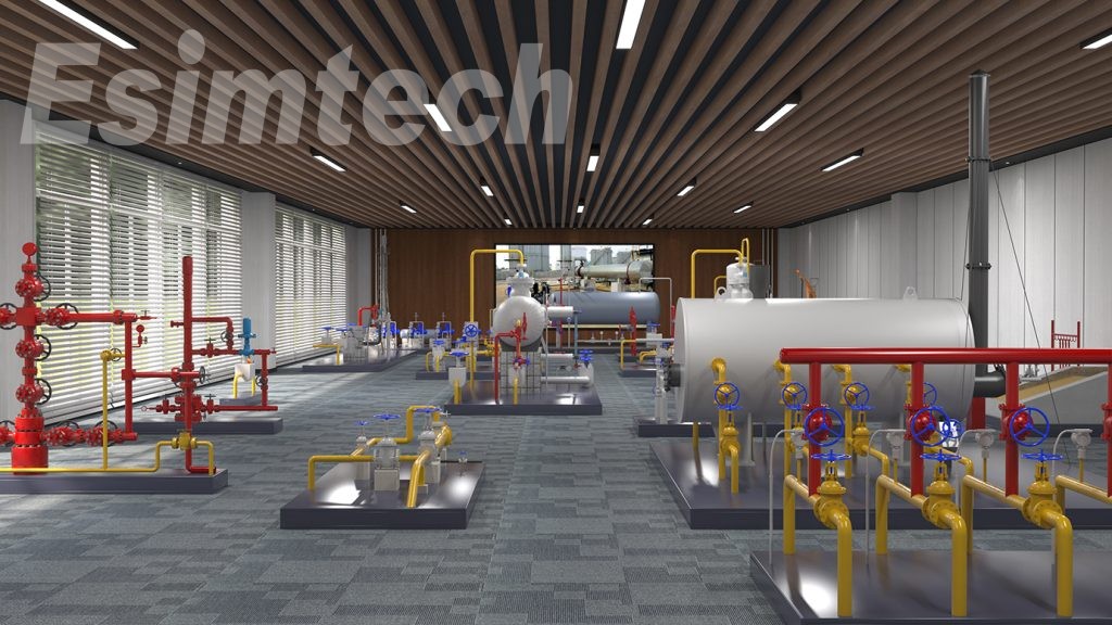
1. Introduction
The gas production simulation training system is designed by Southwest Petroleum University and Chengdu Esimtech Petroleum Equipment Simulation Technology Exploitation Co,Ltd.It is an advanced and fully functional system that satisfies oilfield training.
The gas production simulation training system is a combination of petroleum engineering,computer technology,virtual reality technology,and computer simulation.It can enable students to master the inner structure of various gas production equipment and its working theories,typical stations and process.It provides various layers of training,which satisfies the training requirement of primary workers,intermediate workers,senior workers,technicians and senior technicians.The training provided by this system make the students theories of various gas production devices and usage,as well as the method of treating common accidents.
The system adopts“flow coupling”to calculate the pressure,flow rate and temperature in the pipe.Advanced mathematical model makes the training more immersive.Common accidents and device fault can be set at anytime by the instructor with the use of accident preset technology.The displaying system with large size screen presents the whole process clearly,which make the training more effective by saving time and strengthening the students’understanding.
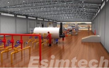
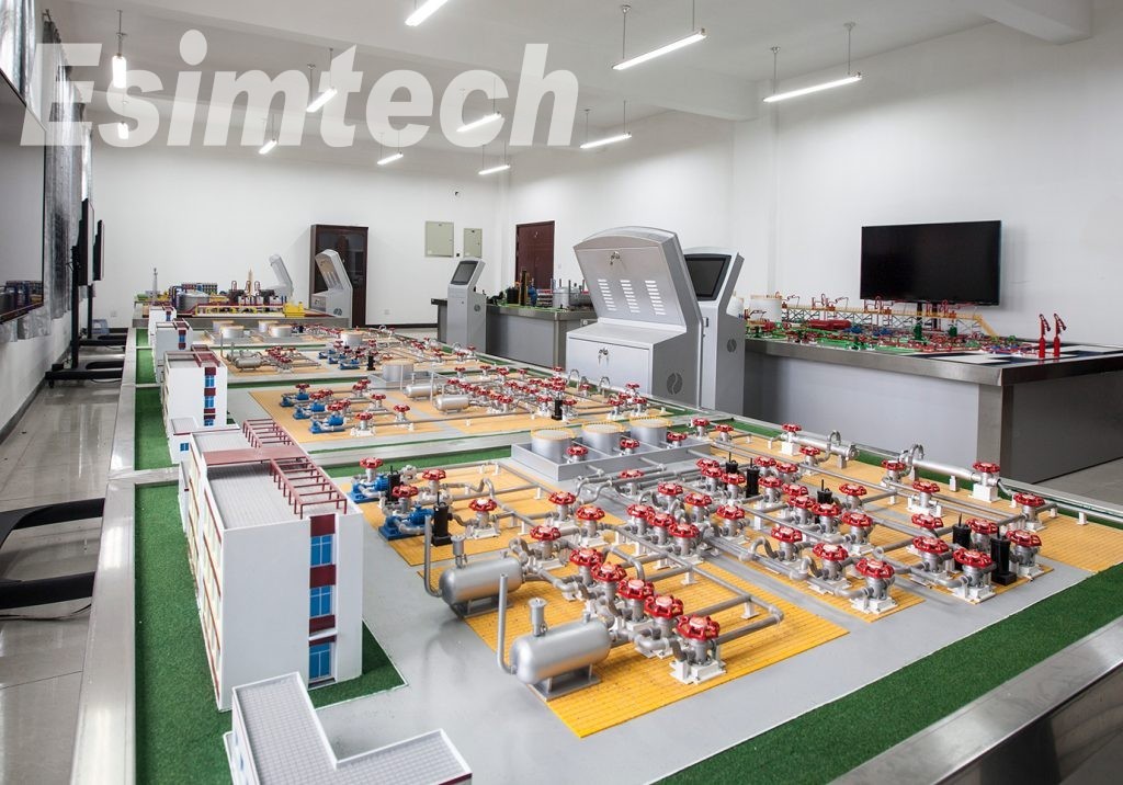
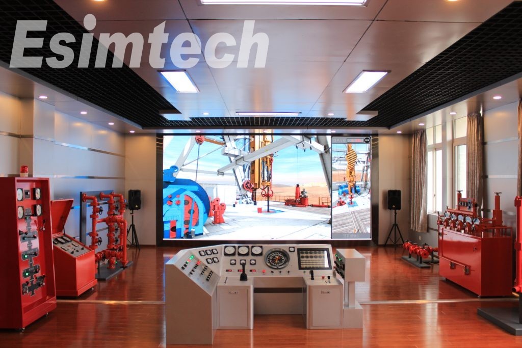
This system consists of gas production simulation platform,graphics system and other accessory software.The consoles of this system are the same as the real equipment.The pipes are made by metal which are sturdy and durable.The panels,operations and parameter displaying are also the same as the real equipment.Hardware system is designed according to industrial standard.Data acquisition and control system adopts PLC which ensures the reliability of the system.This system has low input and maintenance input.All data acquisition is completed by sensors.There is no actual fluid within the devices,no security risks of high pressure or poisonous materials.
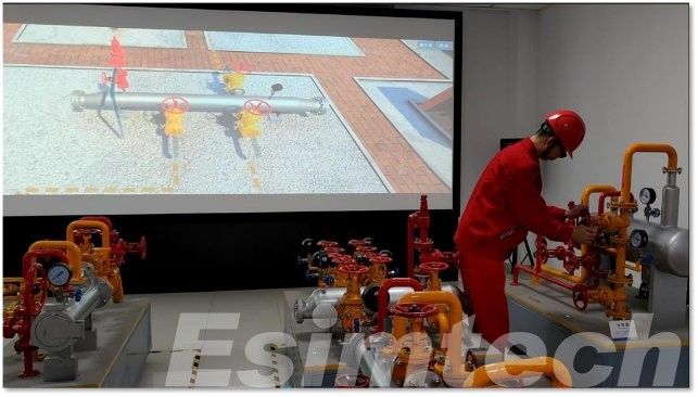
Figure 1 The training site
2. System Component
2.1 Major Hardware
Hardware system layoutisas shown in figure 2.
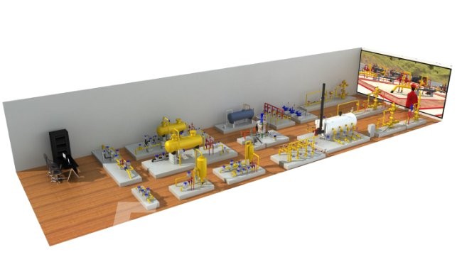
Figure 1 System hardware framework
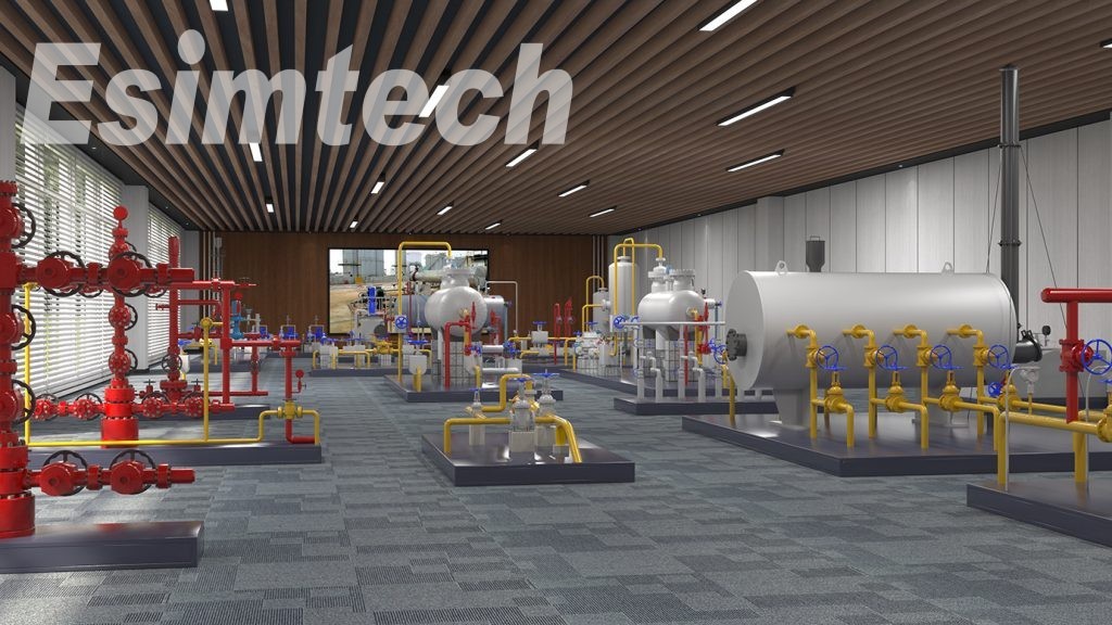
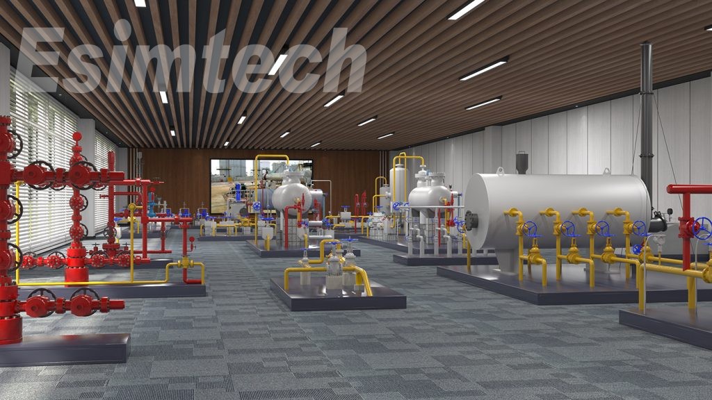
The gas production well training platform is composed of three gas wells respectively used for flowing production,ESP drainage production,plunger drainage production.Gas gathering training platform contains the emptying manifold,antifreeze device,high pressure entrance valve group,heating furnace,production separator,metering separator,choke,pipeline pig,orifice flowmeter,water separator unit;Methanol pump rom training platform includes methanol storage tank,methanol pump.Installation and maintenance training platform contains installation and maintenance operation console,as shown in figure 3.
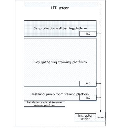
Figure 2 Typical device layout
1.Gas production well training platform
Gas production well training platform is mainly composed of plunger dewater gas production well and electrical submersible dewater gas production well.The valves on gas well are modified on the basis of real valves,with sensors inside.The operation of the valves is the same as real device.Meters are controlled by master control computer at real time.The reading of the meters is linked with students’operation.
|
|
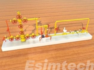
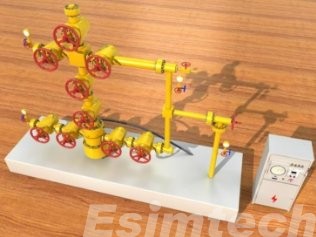
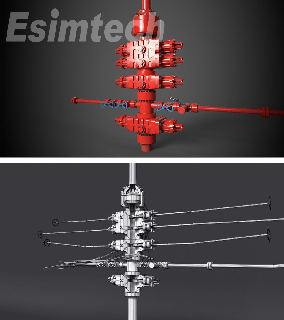
Standard flowing well The gas well is made of mall metal. It is designed by scale according to the onsite typical structure, including the main body of the Christmas tree, 11 main valves, 1 regulating valve, 5 pressure meters, 1 sampling valve, 1 flowing meter and 4 methanol pipeline valves. |
|
|
ESP drainage production well The gas well is made of mall metal.It is designed by scale according to the onsite typical structure,including the main body of the Christmas tree,9 main valves,1 regulating valve,4 pressure meters and 1 sampling valve. |
|
|
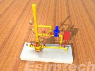
Plunger drainage production well Made of mall metal. It is designed by scale according to the onsite typical structure, including the main body of the plunger drainage Christmas tree, 1 main valve, 5 auxiliary valves, 1 regulating valve and 2 pressure meters. |
Gas gathering station training platform
Gas gathering station training platform is mainly composed of different process modules,such as high-pressure incoming area,water jacket furnace,1st throttling area,production separator,etc.The valves on the modules are modified on the basis of real valves,with sensors inside.The operation of the valves is the same as real device.Meters are controlled by master control computer at real time.The readings of the meters are linked with students’operation.
|
|
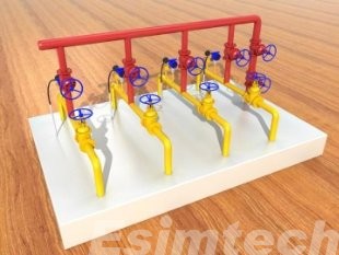
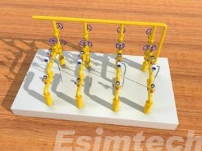
High pressure incoming area Allmetal structure; It is designed according to the real site device by scale, supporting four wells flowing to the station, with emptying pipeline, including pipeline, 10 valves, 4 pressure meters and 3 flow indicator. |
|
|
Water jacket furnace With four incoming and four outgoing pipes and bypass line. Made of metal, designed according to typical structure by scale on real site. The dimension of the furnace is designed and processed according to the installation environment, including water-jacket heating furnace body, pipeline, 8 valves, 4 bypass valves and an igniter valve |
|
|
1st throttling area Four-channel throttling area. Made of metal, designed according to typical structure by scale on real site, including pipeline, 12 main valves, 4 pressure meters before pressure regulating, 4 pressure meters after pressure regulating, and 4 flow indicators. |
|
|
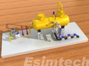
Production separator Made of metal, designed according to typical structure by scale on real site, including the tank body, pipeline, one inlet valve, one outlet valve, two drainage valve, one drainage pressure regulating valve, 4 pressure meters, 1 level indicator and 2 high pressure emptying pipelines (manual and automatic). |
|
|
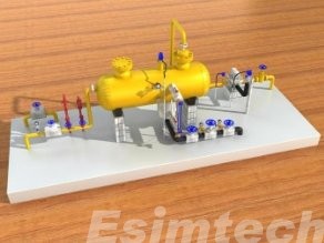
Metering separator With bypass pipes. Made of metal, designed according to typical structure by scale on real site including the tank body, pipeline, one inlet valve, one outlet valve, two drainage valve, one drainage pressure regulating valve, 4 pressure meters, 1 level indicator, 2 high pressure emptying pipelines (manual and automatic) and outflow indicator. |
|
|
Cyclone separator With vent pipes and bypass valve. Made of metal, designed according to typical structure by scale on real site including one inlet valve, two outlet valves, one bypass valve and 2 high pressure emptying pipelines (manual and automatic). |
|
|
Water separator and gas storage unit With metering lines and vent pipes. Made of metal, designed according to typical structure by scale on real site, including 2 inlet valves, 1 outlet regulating valve, 1 inlet bypass valve, 2 high pressure emptying pipelines (manual and automatic), out flow indicator, 3 outlet valves and 1 outlet bypass valve. |
|
|
2nd throttling area Made of metal, designed according to typical structure by scale on real site, including 1 inlet valve, 1 outlet valve, 1 pressure regulating valve, 1 bypass valve, 1 inlet pressure meter and 1 outlet pressure meter. |
|
|
Dosing tank Methanol and foaming agent mixing tank. Designed according to typical structure by scale on real site, including tank body, level indicator, inlet valve, outlet valve, emptying pipeline and booster line. |
|
|
Outgoing valves With metering, pig valve, and filter. Designed according to typical structure by scale on real site, including 1 inlet valve, 1 pressure regulating valve, 1 orifice flowmeter, 2 thermometers, 2 pressure meters, 1 flowing indicator bypass valve, 1 pig sending valve, 1 outgoing valve, 1 pig sending bypass valve, 1 high pressure emptying pipeline. |
Methanol pump section training platform
|
|
Methanol storage tank With vent line, natural gas boosting line and liquid level gauge. Made of metal, designed according to typical structure by scale on real site. This device is designed according to the size of real equipment; it can also be customized according to different region and technology. |
|
|
Methanol pump Three groups of metering pumps. Designed according to typical structure by scale on real site. Each group contains inlet valves, outlet valves and bypass valves. |
Installation and maintenance training platform
|
|
Installation and maintenance operation console This console is used for the primary workers to install and maintain. The console is made of real physical devices, including gate valves, pressure valves, orifice flowmeters and safety valves. |
5. Display system adopts LED screen display.
|
|
Large size LED screen full color display system •The 3D animationisdisplayed on a LED screen after processed by professional graphic processor. •LED P2.5 screen; Resolution: 1920*960 •Screen size: 5400mm(wide)*3215mm(high) (The ultimate installation size and resolution will be depended on installation environment) |
2.2 System Software
2.2.1 Gas production simulator process software
(1) Software framework module
(2) Interface controlling module
(3) Fluid calculating software module
(4) Device controlling software module
(5) Accidents and troubles software module
(6) Sound effect controlling module software
(7) System diagnostic module
2.2.2 Esimtech gas production simulator graphics software
(1) 2D flow control module
(2) 3D flow control module
(3) Equipment control module
3. System configuration
|
SN |
Name |
Unit |
Q’ty |
|
|
1 |
Gas well wellhead console |
Standard flowing production wellwellhead |
Unit |
1 |
|
2 |
Simple flowing production well |
Unit |
1 |
|
|
3 |
Plungerdrainageproductionwellwellhead |
Unit |
1 |
|
|
4 |
ESPproductionwellwellhead |
Unit |
1 |
|
|
5 |
Gas-gathering station module |
Emptyingmanifold |
Unit |
1 |
|
6 |
Antifreezerunit |
Unit |
1 |
|
|
7 |
Highpressureinletvalvegroup |
Unit |
1 |
|
|
8 |
Furnace |
Unit |
1 |
|
|
9 |
Meteringseperator |
Unit |
1 |
|
|
10 |
Pipepig |
Unit |
1 |
|
|
11 |
Orificeflowmeter |
Unit |
1 |
|
|
12 |
Water separator unit |
Unit |
1 |
|
|
13 |
Foamingunit |
Unit |
1 |
|
|
14 |
1stand2nd throttling |
Set |
1 |
|
|
15 |
Intallationandmaintenancetrainingplatform |
Set |
1 |
|
|
16 |
Instructorstation |
Unit |
1 |
|
|
17 |
Mastercontrolcomputer |
Unit |
1 |
|
|
18 |
Graphiccomputer |
Unit |
1 |
|
|
19 |
Printer |
Unit |
1 |
|
|
20 |
Soundeffectsystem |
Set |
1 |
|
|
21 |
Computercabinet |
Set |
1 |
|
|
22 |
Large size LEDscreen |
Set |
1 |
|
|
23 |
Esimtech gas production simulation training system master control software |
Set |
1 |
|
|
24 |
Esimtech gas production simulation training system process software |
Set |
1 |
|
|
25 |
Esimtech gas production simulation training system graphics software |
Set |
1 |
|
4. System Function
4.1 Function and Feature
(1)This system is designed according to the real equipment,that is,the appearance,the connection of the pipes and operation methods are the same as the real equipment.
(2) This system can calculate the parameters according to the students’ operation, such as the working condition and pipe pressure.
(3) 3D animation simulates the visual environment. The animation of the system can display the downhole condition, device motion and working theories of various devices.
(4) The system can simulate the real site noises. The sound complies with the students’operation, working condition and graphics.
(5) Accident setting can enable students to observe the causation of accident directly and master the handling of common accidents.
(6) The system has adjustable gas well parameter (pressure, temperature, flow).
(7) The system has completed expandable function.
4.2 Training Projects
(1) Flowing well startup and shutting in
(2) Plunger pump dewatering well startup andshutting in
(3) Electrical submersible pump dewatering startup and shuttingin
(4) Treatment of natural gas leaking
(5) Injecting anti-freezer
(6) Natural gas venting operation
(7) Starting and shut down furnace
(8) Gas well single well metering
(9) Natural gas dehydrating operation
(10)Pi greceiving and launching operation (Optional; hardware increasing is needed)
5. Technical Parameters and Operational Environment
5.1 Technical Parameters
(1) Power supply:220V/50Hz AC
(2) Power consumption: <6000W
5.2 Operational Environment
(1) Area: >=10*8.5m
(2) Separate equipment power supply fromlightpower supply
(3) Working temperature: 0℃~30℃
(4) Relative humidity: <90%
6. System Layout and Program Interface
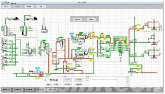
Figure 3 Master control interface
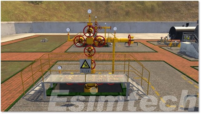
Figure 4 Graphics program running interface 1
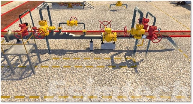
Figure 5 Graphics program running interface 2
F&Q
- What new petroleum simulations and features are you working on?
Esimtech has been committed in study and developing a petroleum engineering simulation training system for about 30 years, and has a series of independent intellectual property rights. Our simulators are widely used in many training companies with good feedbacks. To keep pace with the international standard and demand, Esimtech is now studying and developing MPD simulator, where some achievement has been reached.
- Can this simulator replace the simulators I currently use in my well control training program?
Esimtech drilling and well control simulator has been approved by IADC and IWCF which can be used for common operation training, as well as IWCF and IADC training programs.
- Why is your simulator better than other simulators I’ve used in the past?
With the mission of “Assist training, reduce accidents and benefit the society”, Esimtech have been doing their best to design, develop and service every simulator. Esimtech simulator has its features as strictness, reliability, realisticness, lifelikeness. Problems and incident playback function enables trainees to experience troubles for any time which helps trainees to better master the skills of judging and handling of common troubles.

