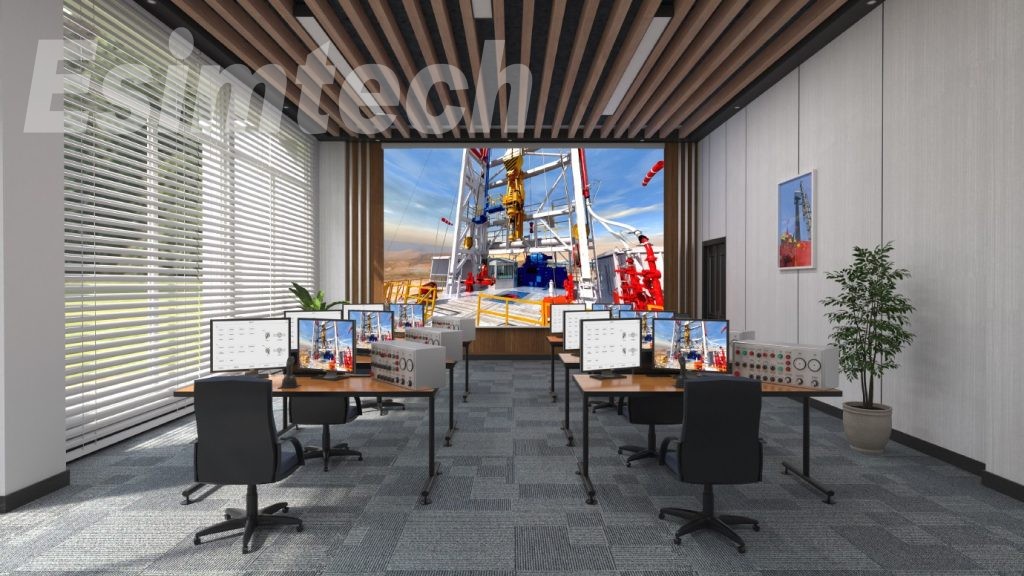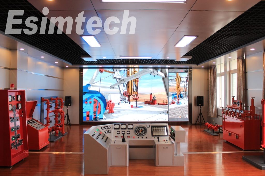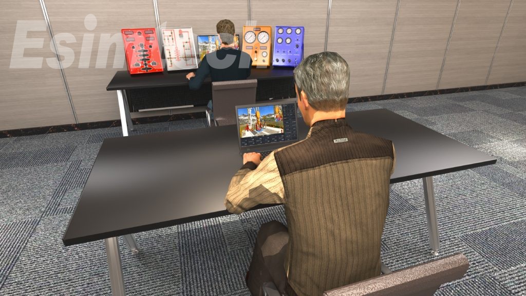
ESIM-PWS3 Portable Workover Simulator
- Non-sequence simulation software structure allows no restriction on operation sequence.
- Simulate the formation kick according to the parameters change such as well depth, mud density formation pressure, etc.
- Operator can record and calculate shut-in tubing pressure and casing pressure at real-time.
- Bottom-hole pressure can be adjusted with choke valve during well killing circulation.
- Killing speed can be adjusted at any time during well killing.
- Killing curves can be generated automatically after well killing.
1. Introduction
Portable workover simulation training system is designed by Southwest Petroleum University and Chengdu Esimtech Petroleum Equipment Simulation Technology Co. Ltd. This system provides trainings on workover well control, featured in easy to carry and complete functions.
Portable workover simulation training system is the combination of petroleum engineering and computer technology, virtual realization technology, computer simulation technology. It is mainly used to train new workers, driller/ assistant driller, drilling technicians and driller supervisors. The training provided by this system can enable trainee to master the basic techniques of shutting in and well killing.
The system adopts mathematical model to simulate various parameters such as pressure, torque, drilling rate, flow rate, etc, and to reflect the relationships between these parameters so as to reach the same effect as the real drilling operation. 3D animation at the real time makes up an immersive environment for the trainees.
The system is composed of portable console, graphics system and accessory software. Hardware system is designed according to industrial standard. Data acquisition and controlling system is completed by PLC, which ensures the reliability of the equipment. The system has the advantage of low input and maintenance cost with no security risk.
2. System Component
2.1 Major Hardware
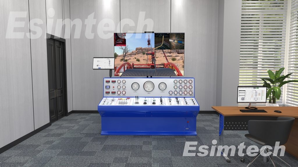
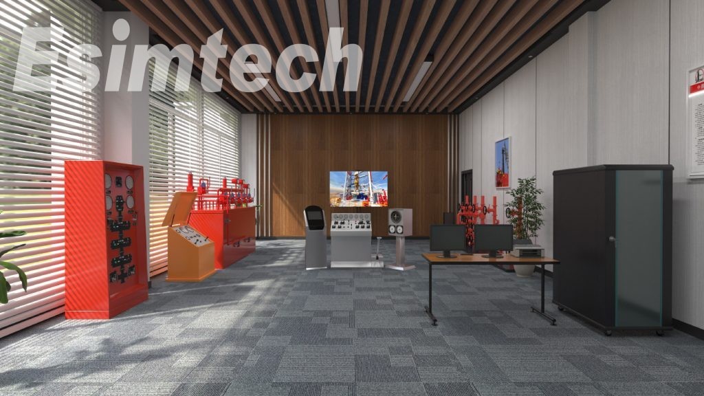
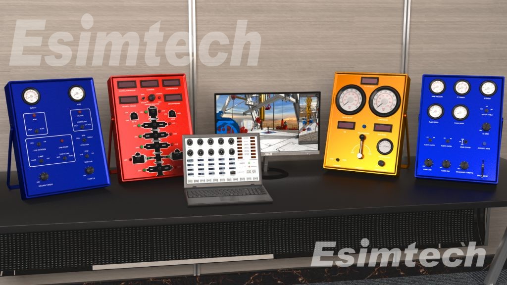
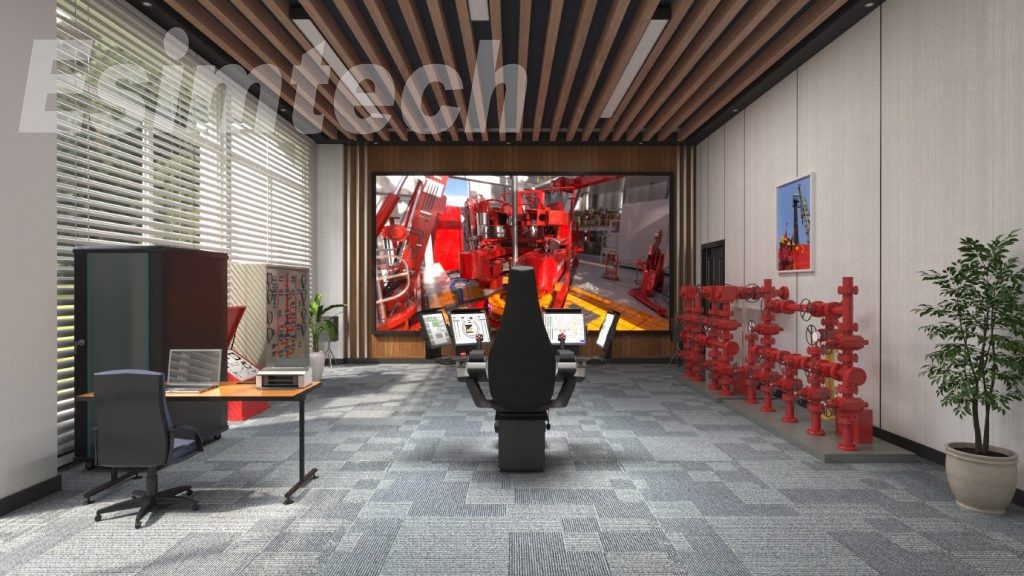
The system consists portable driller console, portable BOP console, portable choke console and portable manifold console. The consoles adopt aluminum alloy cabinet, easy to take around.
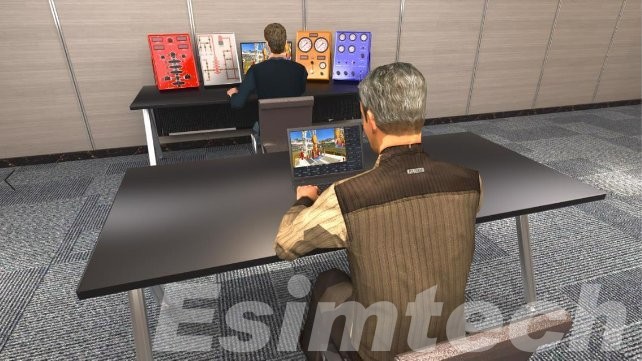
Figure 1 System whole layout
1) Portable driller console
Portable driller console is as shown in figure 2. The control and displaying is the same as real devices. It can simulate drawworks raising and lowering, mud pump speed adjusting, rotary table speed adjusting, etc.
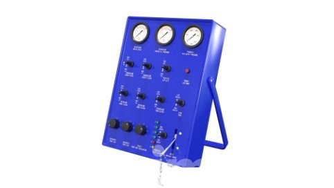
Figure 2 Portable driller console
2) Portable choke console
Portable choke console is as shown in figure 3. Parameters can be displayed on this console such as tubing pressure, casing pressure, kill manifold pressure, pump speed, total stokes, choke position, etc. Hydraulic choke valve position can be adjusted on this console.
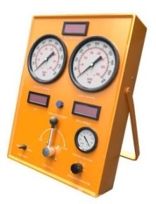
Figure 3 Portable choke console
3) Portable BOP console
Portable BOP console is as shown in figure 4. This console simulates conventional BOP product. The parameters display is the same as in real device. This portable console simulates the control of annular preventer, two pipe rams and one blind ram. Besides. The console can simulate the line-up and close of the hydraulic valves of kill manifold and choke manifold.
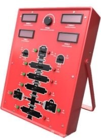
Figure 4 Portable BOP console
4) Portable manifold console
Portable manifold console is as shown in figure 5. This console can simulate the valve control of standpipe manifold, choke manifold, and kill manifold. The system can detect the manifold path automatically according to manifold operation.
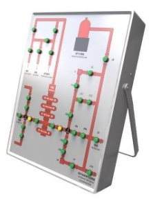
Figure 5 Portable manifold console
2.2 System Software
2.2.1 Master Control Software
a) Student side software module
This module displays the workover parameters, provides alarm setup, and complete the control of 3D scenarios.
b) Instructor station software module
This module provides the setup and modification of parameters such as formation parameters, well structure, drill string assembly, pump parameter, mud system parameters, etc. and provides the displaying of parameters at real-time such as tripping speed, WOB, rotary rate, pit gain/ loss, return flow, pump speed, flow rate, total strokes, etc. In this module, instructor can set measurement unit, system language, and can control simulation speed.
c) Well control software module
This module controls well control operation, and simulates the displays of well control parameters such as casing pressure, tubing pressure, choke position, workover fluid increase/ decrease, bottom hole pressure, etc. Parameters can be displayed in the form of curves at real-time such as tubing pressure, casing pressure, pit gain/ loss, bottom hole pressure, formation pressure.
d) Sound effect control module software
Sound of pumps, drawworks, rotary table, etc. on workover site can be simulated.
e) System diagnostic module
Detecting the working state of hardware devices.
f) Students managing module
2.2.2 Graphics Software
a) Drilling-floor-based (major workover) 3D scenario displaying software module
b) Non-drilling floor-based (minor workover) 3D scenario displaying software module
3. System Configuration
|
Serial No. |
Name |
Unit |
Q’ty |
|
1 |
Portable driller console |
Unit |
1 |
|
2 |
Portable BOP console |
Unit |
1 |
|
3 |
Portable choke console |
Unit |
1 |
|
4 |
Portable manifold console |
Unit |
1 |
|
5 |
Portable computer (CPU: i7; Discrete graphic card) |
Unit |
1 |
|
6 |
Touch screen |
Unit |
1 |
|
7 |
Esimtech portable downhole operation simulator software |
Set |
1 |
4. System Software Function
4.1 Sound effect simulation
There is simulation sound when there is corresponding action in the simulation animation such as device collision, running, speed up/ down, etc. The simulated sound effect is vivid and close to the sound on real site.
4.2 Simulator function
The simulator is mainly used for training workover driller, drilling crew technicians and workover team leaders. Through the training and test of this system, trainees can master the skills of hard shut-in and soft shut-in, and well killing technology of conventional and unconventional well killing.
The system adopts various mathematical models to simulate various working conditions
and parameters of down hole operations, such as pressure, torque, flow rate, etc. and reflect relationships of these parameters to realize training effect of operating on real site.
Workover parameters can be set in the system, such as string structure, well structure, formation parameters, device parameters, etc. which makes training more targeted and flexible. The software adopts non-sequence framework, simulating various operations of workover. Virtual reality technology and 3D animation makes up an immersive training environment.
The simulation system is designed according to industrial standard. Data acquisition and control system is constructed by RTU, which ensures the stability of the system.
4.3 Functions and Features
1) The system adopts non-sequence simulation software structure. There is no limitation to trainee’s operation sequence. Operators can operate the simulations system randomly, just as operating the real workover rig.
2) The simulator can dynamically simulate the formation kick according to the parameters change such as well depth, mud density formation pressure, bottom hole pressure, formation permeability, etc.
3) After simulation shut-in, operator can record and calculate shut-in tubing pressure and shut-in casing pressure at real-time.
4) During well killing circulation, bottom hole pressure can be adjusted by adjusting casing pressure and tubing pressure with choke valve.
5) During well killing, killing speed can be adjusted at any time.
6) After well killing, killing curves can be generated automatically. The curves including tubing pressure, casing pressure, pit gain/ loss, bottom hole pressure, etc.
7) After simulation kick occurs. Any BOP tools can be chosen to installed, such as BOP wellhead, cock, BOP sub, BOP single, etc.
8) During practice and assessment by the simulator. students should observe the parameters and judge the downhole troubles by relevant parameter change.
9) The simulator can simulate two scenarios for practice and assessment: major workover and minor workover.
10) Different parameters can be set in snapshot for practice and assessment, such as formation structure, make-up of string etc.
11) The simulator can record student’s operation at real-time and gives out score according to the operation.
12) The simulator can display workover parameters at real-time such as WOB, rotary rate, tubing pressure, flow rate, mud volume, pit volume, trip tank gain/ loss, well depth, string position, hook height, etc.
13) It has alarm setting function. Trainees can set numerous parameter limits. When parameters exceed the set limit value, the system will launch an alarm. And the launching and stopping of the alarm complies with the trainee’s operation, work condition and also graphics. The parameter alarms that can be set include mud gain/ loss alarm, anti-collision upper and lower limits, etc.
14) The system simulates real site using 3D animation on big screens which shows workover operation scenario, device action and device working principle.
15) The system has trainee information management function.
16) The system can simulate the process of hard shut-in and soft shut-in.
17) The system can simulate shut-in with inside BOP tool in string (such as cock, BOP single).
18) The system provides English unit and Metric unit, which can be switched timely.
19) The system provides Chinese and English language which can be switched timely.
3.2 Training Project
(1) Shutting in operation– Major workover (With drilling floor)
a) Shut-in after kick occurs in running and pulling tubing
b) Shut-in after kick occurs in rotary operation
c) Shut-in after kick occurs in tripping large diameter tool operation
d) Shut-in after kick occurs in wireline perforation operation
e) Shut-in after kick occurs in barren hole
(2) Shutting in operation– Minor workover (Without drilling floor)
a) Shut-in after kick occurs in running and pulling tubing
b) Shut-in after kick occurs in rotary operation
c) Shut-in after kick occurs in tripping large diameter tool operation
d) Shut-in after kick occurs in wireline perforation operation
e) Shut-in after kick occurs in barren hole
(3) Well killing operation
a) Driller’s method of well killing
b) Reverse circulation driller’s method of well killing
c) Engineer’s method of well killing
d) Reverse circulation engineer’s method of well killing
5. Technical Parameters and Operation Environment
4.1 Technical Parameters
-
Power supply: 110~220V/50~60Hz AC
-
Power consumption: 0.3KW
4.2 Operation Environment
-
Temperature: 0℃~ 30℃
-
Relative humidity: < 90%
6. Graphics Program Interfaces
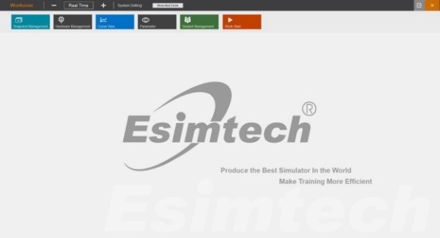
Figure 6 Instructor operation interface
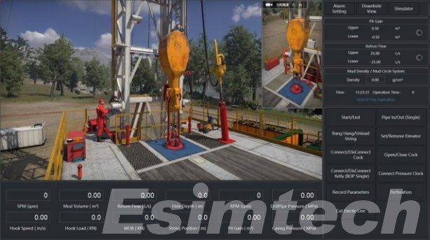
Figure 7 Student operation interface
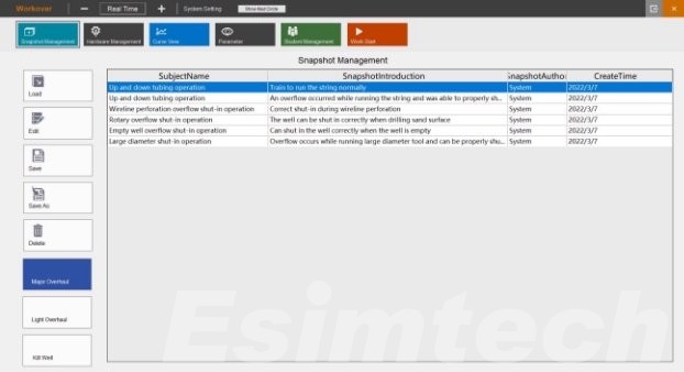
Figure 8 Instructor screen of parameter displaying
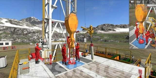
Figure 9 Graphic screen-Major workover (With drilling floor)
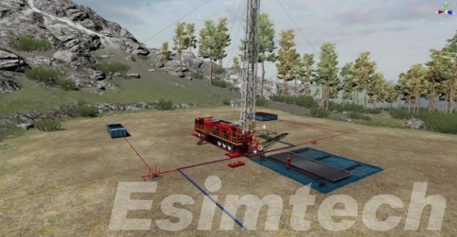
Figure 10 Graphic screen—Minor workover (Without drilling floor)
Our Strength
- Preciseness
- Precise mathematical and physical model
- Reliability
- Stable and reliable software and hardware
- Reality
- Highly realistic 3D scene display
F&Q
- What well control simulations does this well control simulator cover?
In well control operation, pressure control is very important. How the pressure is controlled? In the well control simulator, various scenes of kick can be simulated, both hard and soft shut-in the procedure can be carried out. Meanwhile, various well-killing methods are provided, such as driller’s method, engineer’s method, volumetric method, bullheaded, low choke method, standpipe pressure method, etc.
- What new petroleum simulations and features are you working on?
Esimtech has been committed in the study and developing petroleum engineering simulation training system for about 30 years, and has a series of independent intellectual property rights. Our simulators are widely used in many training companies with good feedbacks. To keep pace with the international standard and demand, Esimtech is now studying and developing MPD simulator, where some achievement has been reached.
- Can this simulator replace the simulators I currently use in my well control training program?
Esimtech drilling and well control simulator has been approved by IADC and IWCF which can be used for common operation training, as well as IWCF and IADC training programs.

